This section contains the reference of all supported protocols, in alphabetical order, grouped by category/vendor.
This the multi-page printable view of this section. Click here to print.
Protocols
- 1: Common Settings for all Protocols
- 2: Axia
- 3: Barix
- 4: D&R
- 4.1: D&R Airlite
- 4.2: D&R Webstation
- 5: DHD
- 5.1: DHD External Control Protocol (ECP)
- 5.2: DHD REST API
- 5.3: DHD RM2200D
- 6: Ember+
- 6.1: Ember+ Consumer
- 6.2: Ember+ Provider
- 7: Generic
- 7.1: HTTP Client
- 7.2: MQTT Client
- 8: Internal
- 8.1: REST API
- 8.2: Virtual Core
- 8.3: XML File Output
- 8.4: Timer
- 8.5: Dummy
- 8.6: Keyboard
- 9: MIDI
- 9.1: MIDI Input
- 9.2: MIDI Output
- 10: Notifications
- 10.1: Variables used in Notifications
- 10.2: SMTP/E-Mail Notifications
- 10.3: Webhooks
- 11: Prodys
- 11.1: Prodys ProntoNet
- 11.2: Prodys Quantum/IkusNet
- 12: USB
- 12.1: Elgato Stream Deck
- 12.2: IOWarrior
- 12.3: Velleman K8055
- 13: Wheatstone
- 13.1: WheatNet Blade ACI
1 - Common Settings for all Protocols
There are some settings which are available for any connection type.
General
On this tab, some general settings about the connection are made:
- ID: Enter a unique ID for this connection. It should only contain
lower case letters, numbers and or the
-sign. - Description: An optional description.
- Location: Entering a value (or choose one from the list) will let you group the connections by location in the application main window (small tabs below the connection list).
- Group: Similar to location; enter a value here to establish logical connection groups, which can be viewed by toggling the tabs below the connection list in the main windows.
- Enable extended debug logging: If enabled, some connection types will output extended debug information to the log.
- Enable status parameters: If enabled, an additional write-only boolean
parameter
_status/connectedwill appear that indicates whether the connection to the target device has been established successfully.
Note
The connection ID will be used throughout the application to identify a connection and its parameters.
Changing the ID of an existing connection will recreate the connection object in the BTConnect engine.
To avoid breaking your configuration, it is advised that you do not change the ID once you have used parameters from this connection in the converter rules etc.
MQTT Bridge
Check Enable MQTT Bridge in order to connect to the MQTT broker defined in the global configuration. Each connection object will establish a separate MQTT client connection to the broker.
- Client ID: In MQTT, each client has a unique “client ID” that is used to identify the client, and possibly catch up with messages missed during an outage. The Client ID defaults to the connection ID set on the General Tab, but you can enter a different value here if you like.
- Topic Prefix: If set, all topics will be prefix with this string,
in addition to the global topic prefix set in the application settings:
<global topic prefix>/<topic prefix>/<connection ID>/val/...
2 - Axia
2.1 - Livewire Routing Protocol (LWRP)
This connection type implements the Livewire Routing Protocol (LWRP).
Supported Devices and Prerequisites
We can connect to all devices that support LWRP, for example any kind of Axia xNode, or the Livewire Driver. The exact capabilities depend of the device and are queried from the device during configuration (see below).
Configuration
General Tab
First, enter IP/hostname and Port (usually 93) of your Livewire device, plus optionally the password if one is set on the device.
In the next step, various properties of the device must be determined:
- The number of Livewire sources and destinations.
- The number of GPIs and GPOs.
- The number of mixpoints.
- The number of inputs.
While you can edit these fields manually, the most convenient
method is to click Retrieve from Device -
BTConnect will briefly connect to the device and issue a
VER command, which returns all the required numbers.
Additional settings:
- GPIO High = false: Livewire uses the value “High” to indicate
an inactive GPIO state. This option - enabled by default -
will use
truefor “High” andfalsefor “Low”, so it is integrated more natural with the rest of the BTConnect system. - Writeable GPIs: On physical devices like xNodes, GPI pins are typically read only (as they report the electrical state of the physical port); but on other devices, most notably the Livewire Driver, GPIs can be written to from the software. Check this option if you want your GPIs to be writeable. If unchecked, GPI pins will become read-only parameters.
- LPSTAT polling: Some devices, in particular xNodes, support
an
LPSTATcommand that returns additional status information about the device, e.g. the uplink status of the ethernet port, or the status of the power supplies. This information can only be retrieved via polling, which you can enable here.
Level Detection Tab
Some Livewire devices (e.g. xNodes) support integrated silence and clip detection for all inputs and outputs.
The availability of this feature, or the number of
inputs/outputs it supports, can not be queried with the VER command,
so it is offered in the configuration regardless of the device you are
using; please refer to the device documentation to find out if
it supports level detection at all.
For each input/output, you can set the target levels (dBFS) and the number of milliseconds after which the event should be reported.
Parameters
LWRP connections provide the following parameters:
General information
device/name(string, read-only) - The name of the device.device/product(string, read-only) - The product name of the device.device/model(string, read-only) - The model of the device.device/version(string, read-only) - The software version of the device.
Status information
Note: only available if LPSTAT polling is enabled
status/temperature(integer, read-only) - temperature of the unit in celsius.status/psu(boolean, read-only) - The status of the internal power supply.status/poe(boolean, read-only) - The status of PoE power supply.status/net0(boolean, read-only) - The status of the first Ethernet port.status/net1(boolean, read-only) - The status of the second Ethernet port.
Livewire sources
source/<id>/name(string, read/write) - The name of the source.source/<id>/enabled(boolean, read/write) - Is the source enabled?source/<id>/address(string, read/write) - The address of the soure.source/<id>/sendaddress(string, read-only) - The current effective RTP multicast address.source/<id>/channels(integer, read-only) - The number of channels (2 or 8).source/<id>/gain(float, read/write) - The volume gain in dB.
Livewire destinations
destination/<id>/name(string, read/write) - The name of the destination.destination/<id>/up(boolean, read-only) - Is the destination up and running?destination/<id>/address(string, read/write) - The source address of the destination.destination/<id>/receiveaddress(string, read-only) - The current effective RTP address.destination/<id>/channels(integer, read/write) - The number of channels (2 or 8).destination/<id>/gain(float, read/write) - The volume gain in dB.
GPIO
gpi/<number>/pin/<number>(boolean, read-only) - the state of the specified GPI and pin (each GPI has five pins).gpo/<number>/pin/<number>(boolean, read/write) - the state of the specified GPO and pin (each GPO has five pins).
Mixer
mixer/<output>/<input>(float, read-write) - the matrix mixer crosspoint, specified as a dB value in the range-1000(off) to0.
Level Detection
input/<id>/silence/left(boolean, read-only) - silence status of the left channel of the input.input/<id>/silence/right(boolean, read-only) - silence status of the right channel of the input.input/<id>/silence/any(boolean, read-only) - silence status of any channel of the input (logical OR ofleftandright).input/<id>/silence/both(boolean, read-only) - silence status of both channels of the input (logical AND ofleftandright).input/<id>/clip/left(boolean, read-only) - clipping status of the left channel of the input.input/<id>/clip/right(boolean, read-only) - clipping status of the right channel of the input.input/<id>/clip/any(boolean, read-only) - clipping status of any channel of the input (logical OR ofleftandright).input/<id>/clip/both(boolean, read-only) - clipping status of both channels of the input (logical AND ofleftandright).output/<id>/silence/left(boolean, read-only) - silence status of the left channel of the output.output/<id>/silence/right(boolean, read-only) - silence status of the right channel of the output.output/<id>/silence/any(boolean, read-only) - silence status of any channel of the output (logical OR ofleftandright).output/<id>/silence/both(boolean, read-only) - silence status of both channels of the output (logical AND ofleftandright).output/<id>/clip/left(boolean, read-only) - clipping status of the left channel of the output.output/<id>/clip/right(boolean, read-only) - clipping status of the right channel of the output.output/<id>/clip/any(boolean, read-only) - clipping status of any channel of the output (logical OR ofleftandright).output/<id>/clip/both(boolean, read-only) - clipping status of both channels of the output (logical AND ofleftandright).
Input Status
input/<id>/aessync(boolean, read-only) - sync status of the AES input (dynamic parameter, will only appear for AES inputs)
3 - Barix
3.1 - Barix Barionet (ASCII)
This connection type implements the Barix Barionet ASCII protocol. It supports the Barionet 50 and 100 devices.
Configuration
Network Connection
Enter the IP adress or hostname of the Barionet device.
For TCP connection mode, enter the TCP port number into the Port field and leave the Use UDP option unchecked.
For UDP connection mode, enter the UDP port number into the Port field, check the Use UDP option and enter a local UDP port number; the same port number must be configured in the Barionet device.
I/O
Click Retrieve from Device to connect to the blade and retrieve the relevant properties of the particular model. This will only work in TCP mode. For UDP mode, you must enter the numbers manually.
Parameters
The connection provides the following parameters:
analog/<id>/in(float, read-only) - value of the analog inputs.analog/<id>/out(float, write-only) - set value of an analog output.digital/<id>/in(boolean, read-only) - value of the digital inputs.digital/<id>/out(boolean, write-only) - set state of a digital output.ir/<id>/out(boolean, write-only) - set state of an IR output.relay/<id>(boolean, read/write) - state of a relay output.temperature/<id>(float, read-only) - reading of a temperature sensor.
4 - D&R
4.1 - D&R Airlite
This protocol
Note
The D&R Webstation uses the identical protocol. The information on this page also applies to the Webstation protocol. Differences between the protocols are noted here.Supported Devices and Prerequisites
This protocol supports the D&R Airlite analog broadcast console.
The Airlite Control software must be running, typically on the same computer, and UDP ports must be set up correctly. Please refer to the manual provided by D&R.
Configuration
The following protocol-specific settings are available in the configuration dialog:
- IP/Hostname: Enter the IP or hostname on which the Airlite Control software is running. Typically this is on the same computer (127.0.0.1)
- UDP Send/Receive Ports: These must match the ports configured in Airlite Control.
Parameters
The following parameters are provided by this connection type:
Channels
Channel number are 1 through 8 (or 6 for the Webstation).
channel/<number>/on(boolean, read/write) - status of the channel ON buttonchannel/<number>/fader(boolean, read-only) - status of the channel fader (falseif set to -∞)channel/<number>/start(boolean, read-only) - combination ofonandfaderchannel/<number>/cue(boolean, read/write) - status of the channel CUE button
Buttons
Button IDs are 1a through 8a and 1b through 8b for the two columns of
eight buttons each
button/<id>/press(boolean, read-only) - will betrueas long as the user is pushing the button downbutton/<id>/color(string, write-only) - change the LED of the button
The following values are available for the button LEDs:
- Solid color:
offredgreen
- Flashing:
red/off/slowgreen/off/slowred/green/slowred/off/normalgreen/off/normalred/green/normalred/off/fastgreen/off/fastred/green/fast
Status
status/silence(boolean, read-only) - Silence detection statusstatus/micon(boolean, read-only) - Any microphone onstatus/nonstop(boolean, read-write) - Non-Stop function activated
4.2 - D&R Webstation
The D&R Webstation is a smaller version of the D&R Airlite, with the following notable differences:
- Number of faders (Airlite: 8, Webstation: 6)
- Number of cart buttons (Airlite: 16, Webstation: 12)
- UDP ports for communication with the control
Apart from that, the Webstation protocol is identical to the Airlite. Please refer to the Airlite protocol documentation for configuration and usage instructions.
5 - DHD
5.1 - DHD External Control Protocol (ECP)
This connection type implements the DHD External Control Protocol (ECP) for mixing consoles and routers from DHD.audio GmbH.
Supported Devices and Prerequisites
The following devices are supported:
- All series 52 cores and consoles
- RM4200D
- Fully supported if running on Firmware 5.x
- Partial support for Firmware 4.x (routing not implemented at this time)
Only TCP/IP connections are supported, no serial port connections.
Configuration
General Tab
Connection-specific settings:
- Network connection: Enter IP/host and port number (usually 2008) of the core.
- Fader Level Notification (only supported for Firmware 7.x): Choose either Channel-based or Fader-based to enable instant notification of fader level, either based on fader channels or by physical faders.
Elements Tab
Click the Load Toolbox Data to import information about your core
from an Extended DHD AudioID/LogicID Export (*.dpx) file.
This file can be created from the DHD Toolbox application (Project -> Export -> Export AudioIDs/LogicIDs).
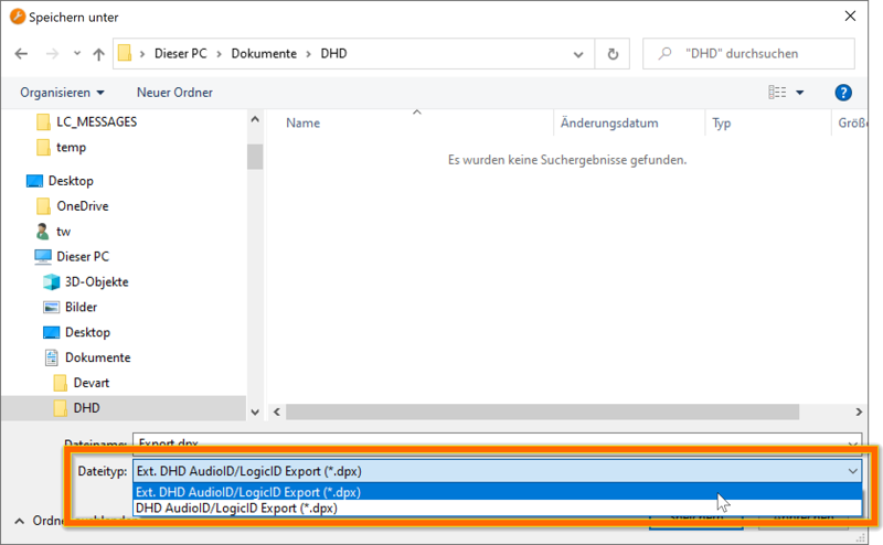
Important
Make sure that you set the file type to Extended (Ext.) output in the Save dialog in Toolbox.After importing the file into BTConnect, the various tabs (Logics, Channels, Routings) will be filled with the IDs and descriptions from the Toolbox file. (If there is more than one device in your Toolbox project, and thus in the export file, you will be first asked which device should be imported for this connection.)
Additional information can be entered manually on the tabs:
- Logics: Enter an optional description that will be used in the GUI rather than the default string imported from Toolbox. Optionally, check a logic for which the current state should be queries when BTConnect starts. (All other logics remain in “unknown” state until the first update is received from the core.)
- Channels: Enter an optional description for each fader channel.
- Faders: Enter an optional description for each fader of each virtual mixer.
- Routing: Check the Req box in order to request the state of a particular routing on startup. Check Enable routing crosspoint notifications in order to receive instant updates when routing changes.
Parameters
The following parameters are provided by ECP connections:
Logics
logic/<id>(boolean, read/write) - the state of the logic with the number<id>(1-4095)
Fader Channels
<number> refers to channel number as given in Toolbox.
channel/<number>/start(boolean, write-only) - switch channel on or off. Note: This parameter is write-only, the current state can only be retrieved via logics.channel/<number>/pfl(boolean, write-only) - turn PFL on or off. Note: write-only, use logics to retrieve status.channel/<number>/level(float, write-only or read/write) - set fader of the channel to the specified level (in dB, range -32.768..+10). If Level Notification is set to “Channel-based” in the configuration, this parameter is read/write, and indicates current fader level, e.g. when operated manually on the console.channel/<number>/timedlevel(string, write-only) - set fader of the channel to the specified level (in dB, range -32.768..+10), within the specified time (in milliseconds) and with a curve of either level linear (0) or fader linear (1). The value must be encoded as a string in the form<level>,<time>,<curve>, or just<level>,<time>; in the latter case, linear fade (0) is used.
Faders
<mixer> refers to virtual mixer (1..4).
<fader> refers to fader (1..48) of that virtual mixer.
mixer/<mixer>/fader/<number>/start(boolean, write-only) - switch fader on or off. Note: This parameter is write-only, the current state can only be retrieved via logics.mixer/<mixer>/fader/<number>/pfl(boolean, write-only) - turn PFL for this fader on or off. Note: write-only, use logics to retrieve status.mixer/<mixer>/fader/<number>/level(float, write-only or read/write) - set fader to the specified level (in dB, range -32.768..+10). If Level Notification is set to “Fader-based” in the configuration, this parameter is read/write, and indicates current fader level, e.g. when operated manually on the console.mixer/<mixer>/fader/<number>/timedlevel(string, write-only) - set fader to the specified level (in dB, range -32.768..+10), within the specified time (in milliseconds) and with a curve of either level linear (0) or fader linear (1). The value must be encoded as a string in the form<level>,<time>,<curve>, or just<level>,<time>; in the latter case, linear fade (0) is used.
Potentiometer (Monitor Level)
potentiometer/<id>(float, write-only) - Level of the potentiometer/monitor channel (in dB)
Routing
routing/<output ID>(string, read/write) - the input audio ID of the signal currently routed to the specified output audio ID. Audio IDs are specified as a 4-digit (Toolbox 4) or 8-digit (Toolbox 5-9) hex number.
Routing is generally based on mono channels in a DHD system, so all outputs are mono, and all inputs are mono as well; thus, a stereo output (input) is represented by two mono outputs (inputs), and in order to route a stereo input to a stereo output, two mono routes must be set.
In order to facilitate the routing of stereo signals, BTConnect will create three parameters for all stereo outputs: one for the left channel, one for the right channel, and one “virtual” stereo parameter (with the stereo bit set in the audio ID). Assigning a mono input ID to this virtual stereo parameter will route that mono signal to both outputs; setting it to a stereo audio ID (with the stereo bit) will send two routing commands for the left and the right channel.
Note
In order to change the output of a stereo Selector with routing parameters, “Source list accepts external routings” must be checked in the Selector configuration in Toolbox. This is because two separate ECP packets are sent in order to change the stereo routing, and the system must be in an “allowed state” in between these to packets.5.2 - DHD REST API
This protocol implements the DHD REST API.
Supported Devices and Prerequisites
All DHD Series 52 cores, running on Firmware 9.1+ and having the REST API license enabled, are supported.
Configuration
On the General Tab, enter IP and port of the core, and the WebApps API token defined in Toolbox.
For picture upload, you can specify an optional Picture folder which is used
as the base for relative filenames supplied to the picture/<id> parameter.
Parameters
Channels
channel/<id>/label(string, write-only) - Update the label of the fader channel with the specified iD.channel/<id>/snapshot(integer, write-only) - Load a channel snapshot. The value is the snapshot number.
Global Labels
globallabel/<id>(string, write-only) - Update a global label.
Picture Upload
picture/<id>(string, write-only) - Upload and replace the picture with the specified resource ID (see Toolbox). The value must be the valid filename of a PNG file, either an absolute filename, or a relative filename in the picture folder set in the configuration.
Snapshots
mixer/<id>/snapshot(integer, write-only) - Load a mixer snapshot.IDis the number of the virtual mixer in the range1..4. The value is the snapshot number.
5.3 - DHD RM2200D
This connection type implements the remote control protocol for the DHD RM2200D.
Supported Devices and Prerequisites
This protocol supports the DHD RM2200D. Communication is through TCP, so the DSP core must be connected with the network.
Configuration
On the General tab, enter the IP address and the TCP port for the remote control protocol (usually 2200).
Parameters
This connection type provides the following parameters:
Main Control Unit
main/button/<button>(boolean, read-only) - the press state of the respective button on the main control unitmain/lcd/1andmain/lcd/2(string, read-only) - the texts currently displayed in the two-line LCD of the main control unit
Faders
Fader numbers are 1 through 16.
fader/<number>/source(integer, read/write) - the ID of the audio source currently assigned to this faderfader/<number>/on(boolean, read/write) - the status of the fader ON functionfader/<number>/cue(boolean, read/write) - the status of the fader CUE functionfader/<number>/button/<button>(boolean, read-only) - the press state of the respective button on this fader stripfader/<number>/led/<led>(boolean, read-only) - the state of the respective LED on this fader stripfader/<number>/status/<status>(boolean, read-only) - theinputstate,timer,faderstartandloadsetupstate of this fader strip
6 - Ember+
6.1 - Ember+ Consumer
This protocol implements a client (consumer) connection to an Ember+ Provider.
Supported Devices and Prerequisites
We can connect to all devices that implement an Ember+ provider.
The connection can currently only handle Ember+ parameters of the type string, integer, float and boolean. All other parameters are ignored during enumeration.
Configuration
On the General tab, enter IP and port of the Ember+ provider.
Parameters
Parameters are fully dynamic in an Ember+ connection. BTConnect will enumerate the Ember+ tree at startup and propagate its own parameter tree accordingly. Value types and readable/writable flags will be the same as in the Ember+ tree.
Parameter Filter
If you want to limit the Ember+ tree to certain subtrees, go to the Filter tab and enter one or more Ember paths. These are treated as subtrees, e.g. if you enter
Device
Channels
only the Ember+ nodes that start with Device/... or Channel/... will become
available as parameters.
Matrix Support
BTConnect provides limited support for the Ember+ Matrix Extension, allowing you to monitor and set crosspoints on matrixes provided over Ember+.
The support is “limited” by the fact that BTConnect does not have a matrix type of its own, so the Ember+ matrix must be translated into one or more string or numeric parameters.
On the General tab of the connection properties, you can choose between four different modes:
Disabled
Matrix support is disabled, matrix notes will not become available as parameters.
Write-Only (One String Parameter)
The matrix will be represented by a single write-only parameter that can be used to set or clear crosspoints.
Note
You must use numeric IDs for the crosspoints which can be looked up inEmberPlusView.exe.
Examples:
-
Set crosspoint - source 1 to target 7:
7:1 -
For n-to-m-matrixes, set two sources (1 and 2) to target 7:
7:1,2 -
For n-to-m-matrixes, add another source to the existing set:
7:+3 -
For n-to-m-matrixes, remove a source from the existing set:
7:-3 -
Multiple commands can be sent at the same time, delimited with spaces (e.g. source 1 to target 7 and source 2 to target 8):
7:1 8:2
Simple (One String Parameter)
This is similar to Write-Only, with a single string parameter representing the matrix - but this time, it is read-write, and the value represents the current state of the matrix, in the same syntax as used for the updates above.
Extended (One Parameter per Target)
In this mode, each target in the matrix is represented by a separate read-write string parameter.
Note
This mode should only be used for matrixes with a low number of targets!You can send string values to the target nodes in order to update
crosspoints for that target, similar to the syntax above, but
with out the target: prefix.
-
Set target to source 1:
1
-
Set target to source 1 and source 2 (n-m-matrix):
1,2
-
Add source 2 to target:
+2
-
Remove source 2 from target:
-2
In addition to the per-target parameters, a top level write-only string parameter will be available, representing the entire matrix, which accepts multi-crosspoint updates similar to Write-Only mode described above.
6.2 - Ember+ Provider
The Ember+ Provider connection exposes the entire BTConnect parameter tree as an Ember+ tree, to be used with third-party Ember+ consumers.
Configuration
TCP Settings
On the General tab, the following settings are available:
- Port: The default port number is 9000.
- Bind IP: Enter an IP adress here to bind to a specific local interface. Default is to listen on all interfaces.
- Keepalive Interval: Interval in seconds of keepalive requests sent to each connected consumer.
- Keepalive Timeout: The consumer connection will be terminated if no reply to a keepalive request was received within this period.
Filter
If you select a specific connection, only the parameters from that connection will be exposed through the Ember+ provider, without any prefix.
If no connection is selected, the entire parameter tree, including all
connection, will be exposed, in the form <Connection ID>/<Parameter>.
Additionally, you can enter on or more filters, in order to limit the exposed tree to only parts of the entire parameter tree.
Values entered here are processed as Perl-compatible regular expressions.
Parameters
The Ember+ Provider connection does not provide any parameters.
7 - Generic
7.1 - HTTP Client
This protocol allows you to fetch data from an HTTP server using GET requests.
Supported Devices and Prerequisites
The HTTP Client connection can fetch data from any HTTP or HTTPS URL.
Optionally, basic authentication or bearer authentication (token) is supported.
Configuration
The following configuration settings are available:
Server configuration:
- URL: This is the URL that the HTTP GET request is performed on.
- Auth User and Auth Password: Fill in values here if your server requires HTTP Basic authentication.
- Auth Token: Enter an optional token if your server uses HTTP Bearer authentication.
Options:
- Polling Interval: Enter the interval (in milliseconds) between two HTTP calls. The default is 5000 milliseconds (five seconds).
- Enable Polling: Uncheck to disable automatic polling. In this case,
the HTTP request will only be performed when the
triggerparameter is used (see below). - Parse Mode: Select the desired mode in which the content returned
by the server is parsed (or not).
The currently supported modes are
NoneandJSON. See the Parameters section below for details.
Parameters
A write-only trigger parameter is provided which can be used to manaully
trigger an HTTP call, whether or not periodic polling is enabled.
When automatic polling is disabled, this is the only way to fetch
HTTP data from the server.
The received data is provided under in data part of the parameter tree.
It depends on the parsing mode set in the configuration:
No Parsing
In parsing mode None, the data returned from the server is exposed as a
single read-only string parameter data.
JSON Parsing
In parsing mode JSON, the returned document is considered a JSON document
(regardless of the Content-type returned by the server), and it is
parsed into a parameter tree (with data as the root) that corresponds
to the JSON document.
Any kind of JSON value (object, array, string, number, boolean) is supported at any level of the tree.
- JSON strings will be turned into string parameters.
- JSON booleans will be turned into boolean parameters.
- JSON numbers will be turned into integer or float parameters, depending on whether the number is a whole number or not.
- JSON objects will be turned into sub-trees.
- JSON arrays will be turned into indexes subtrees, starting with
0.
For example, the following JSON document
{
	"event": "meeting",
	"room": 12,
	"people": [
		{
			"first_name": "Joe",
			"last_name": "Smith",
		},
		{
			"first_name": "Mary",
			"last_name": "Miller",
		}
	]
}
will be translated into these parameters and values:
data/event(string):meetingdata/room(integer): 12data/people/0/first_name(string):Joedata/people/0/last_name(string):Smithdata/people/1/first_name(string):Marydata/people/1/last_name(string):Miller
All parameters are read-only.
7.2 - MQTT Client
This protocol connects to an MQTT broker and allows you to subscribe to and publish MQTT topics as parameters.
Supported Devices and Prerequisites
The MQTT Client can connect to any MQTT broker that supports plain TCP or SSL/TLS connections.
Optional username/password authentication is supported.
Configuration
Network settings:
- Host: The hostname or IP address of the MQTT broker.
- Port: The port number to connect to. The default is
1883(the standard MQTT port). For SSL/TLS connections the typical port is8883. - Use SSL: Check this option to connect using SSL/TLS encryption.
- Client ID: The MQTT client identifier sent to the broker. Each client connecting to a broker must use a unique client ID. If left empty, the broker may assign one automatically.
- User and Password: Fill in values here if your broker requires authentication.
Topics:
- Subscribed Topics: Enter one topic filter per line. The connection
will subscribe to these topics on the broker, and incoming messages
will be exposed as readable parameters. Standard MQTT wildcard characters
(
+for a single level,#for multiple levels) are supported. - Published Topics: Enter one exact topic per line. These topics will be exposed as writable parameters, and writing to them will publish a message to the broker. Wildcard characters are not allowed here.
- Allow Any Publish: If enabled, BTConnect will publish to any valid MQTT topic that is written to, not just the topics listed under Published Topics. This is useful when the target topic is determined dynamically at runtime via converter rules.
If a topic appears in both Subscribed Topics and Published Topics, the corresponding parameter will be both readable and writable.
The connection will automatically attempt to reconnect to the broker every five seconds if the connection is lost.
Parameters
Each configured topic becomes a string parameter in the parameter tree. The parameter path matches the topic name exactly.
Parameter access depends on where the topic is configured:
- Topics listed only in Subscribed Topics: read-only — updated when a message is received from the broker.
- Topics listed only in Published Topics: write-only — writing the parameter publishes a message to the broker.
- Topics listed in both: read/write.
All parameter values are strings. Incoming message payloads are decoded as UTF-8.
8 - Internal
8.1 - REST API
Configuration
On the General tab, the following settings are available:
HTTP Server
- Port: The default port number is 17011.
- Bind IP: Enter an IP adress here to bind to a specific local interface. Default is to listen on all interfaces.
- Document Root: The root folder for the file hosting feature (see below).
Authentication
The HTTP server supports optional authentication, either through HTTP Basic Auth (username and password), or HTTP Bearer Auth (using a base64-encoded bearer token).
If both username/password and token are set, you can any of these to access the server.
Note
If you leave all fields empty (the default), all endpoints can be accessed anonymously.WebSocket
Here you can enter an optional list of filters (as regular expressions) for the WebSocket notifications (see below).
Parameters
The REST API connection does not expose any parameters.
Endpoints
The REST API provides the following HTTP endpoints:
Parameters
The current value of a parameter can be queried with:
GET /parameters/<Connection ID>/<Parameter ID>
e.g.
GET /parameters/dhd-studio1/logic/87
If you set the Accept header to application/json, the value
will be encoded as a JSON value (string, number, or boolean).
Otherwise it will be sent as a plain string.
If the state of the parameter is currently unknown, you will receive
a 503 State Unknown reply.
Parameters can be updated with a request to
GET /update
or
POST /update
It expects two parameters in the GET request (or POST body):
parameter=<Connection ID>/<Parameter ID>
value=<new value>
Values are always encoded as a string and will be typecasted to the correct value type automatically.
WebSockets
The REST API provides a WebSocket endpoint under /ws which
can be used to receive incoming parameter updates in realtime.
Notifications are sent as JSON objects of the following form:
{
  p: "<Connection ID>/<Parameter ID>",
  v: "<new value>"
}
In order to keep traffic as low as possible, you can limit the parameters to specific subtrees in the configuration.
Parameters can also be updated through the WebSocket connection by sending
back JSON objects of the same form. The v part of the object can also
be any other JSON type (not just string) and will be converted
automatically.
File Hosting
The REST API server can also act as a regular web server, hosting static HTML and other files.
To enable this feature, copy all content to a folder of your choice, and set it as the Document Root in the configuration.
The files will be served directly under the main / directory
of the service. You cannot host any files with names that conflict
with the built-in endpoints (/ws, /parameters, etc.).
8.2 - Virtual Core
8.3 - XML File Output
This connection type writes an XML file whenever a parameter value changes. It uses a configurable XML template with placeholders that are replaced with the current parameter values each time the file is written.
Configuration
- Filename: The path and name of the XML file to be written. You can use the Browse button to select or create a file.
- Template: An XML document that serves as the template for
the output file. Any occurrence of
$VariableNamein the template — both in text content and in attribute values — will be replaced with the current value of the corresponding parameter before the file is written.
The template must be a valid XML document. BTConnect will validate it on startup and report an error if it cannot be parsed.
Variables
Variables are defined implicitly by the placeholders in the template.
Any $Name pattern (where Name consists of letters and digits)
found in the template becomes a write-only parameter.
For example, a template like:
<?xml version="1.0" encoding="UTF-8"?>
<status source="$Source">
  <state>$State</state>
  <level>$Level</level>
</status>
will create parameters Source, State, and Level.
Each time any of these parameters is set, all placeholders in the template are replaced with the current values and the resulting XML is saved to the configured file.
Parameters
The parameters are derived from the $Name placeholders found in the template.
For each unique placeholder name, one parameter is created:
<Name>(string, write-only) - Setting this parameter replaces all occurrences of$Namein the template and rewrites the output file.
8.4 - Timer
This connection type provides timers and pulses.
Timers are started by sending any value to their start parameter.
If the value is a number, it will be used as the duration (in milliseconds),
otherwise the default duration set in the configuration will be used.
When the specified time has elapsed, the trigger parameter will send a
Trigger value.
Pulses continuously send triggers in fixed intervals.
Configuration
Timers
Each Timer connection provides up to 16 timers. For each timer, you can adjust
the duration after which its trigger parameter is triggered (unless a specific
duration is sent to the start parameter). The default is 1000 milliseconds.
Pulses
You can define up to 16 pulses.
Check the Enabled box for those pulses that you intend to use, and
adjust the duration (in milliseconds) as required.
Parameters
timer/<id>/start(integer, write-only) - Set to a number to start the timer with the specified duration in milliseconds. If you connect this to a boolean or trigger parameter in the Protocol Converter, the timer will be started with the default duration set in the configuration.timer/<id>/trigger(trigger, read-only) - will be triggered as soon as the duration has elapsed after starting the timer withstart.pulse/<id>(trigger, read-only) - will be triggered periodically according to the interval set in the configuaration.
8.5 - Dummy
The Dummy connection provides an arbitrary number of user-definable parameters which can be used as intermediate storage.
Configuration
On the Parameters tab, enter the list of parameters you wish to define, one parameter per line, in the following form:
<Parameter ID>[,<Value Type>[,<Default Value>]]
The Parameter ID must follow the syntax rules for valid parameter ID;
in particular, it can use the / sign to build hierachies/trees.
The Value Type can be one of
S (string).
B (boolean),
I (integer),
F (float) or
T (trigger).
The default value type is string.
The parameter will be set to the Default Value, if specified, when the connection starts. If no default value is given, its value will be undefined until it is set manually or from a Protocol Converter rule or any API (e.g. MQTT Bridge).
Parameters
The connection will expose the parameters defined in the configuration. All parameters are read-write, and of the type specified in the configuration.
8.6 - Keyboard
This connection type provides two things:
- “Input keys” - system-wide hotkeys represented by read-only trigger parameters.
- “Output keys” - write-only trigger parameters that simulate a keystroke on your computer.
Configuration
Input Keys
On the Input Keys tab, enter one or more keys (or key combinations) that should be available as hotkeys.
You can specify the keys manually (such as ctrl-f1), or use the input field
at the bottom of the tab, press the desired key combination, and then click Add
to add it to the list.
Note that all hotkeys will be global, i.e., the will be available regardless of whether the application is in the foreground or not. As a consequence, the keys combinations will not be available in any other application anymore.
Output Keys
On the Output Keys tab, enter one or more key combinations that you intend to use as virtual keys, triggered by a parameter (see below).
Again, you can use the input field and the Add button to conviently add the desired key combinations.
Parameters
input/<key combination>(trigger, read-only) - Will be triggered when the respective key (combination) is pressed by the user. Due to limitations imposed by Windows, the parameter will not be triggered until the user releases the key(s) again.output/<key combination>(trigger, write-only) - Trigger this parameter to virtually “press” the key combination.
9 - MIDI
9.1 - MIDI Input
This connection type listens to a MIDI input device and exposes incoming MIDI messages as read-only parameters.
Each received MIDI short message is mapped by its raw status byte and first data byte. The second data byte is then published as the parameter value.
This makes it possible to react to note, controller, program change, and other MIDI messages directly in BTConnect.
Configuration
- Device: Select the MIDI input device to listen to.
BTConnect opens the selected device when the connection starts.
Parameters
The MIDI Input connection provides a fixed set of read-only integer parameters in the form:
<status>/<data1>(integer, read-only) - receives the value of the second MIDI data byte (data2) for incoming messages with the specified status byte and first data byte.
The valid ranges are:
status:0to255data1:0to127- parameter value (
data2):0to127
For example:
144/60receives the velocity value for a MIDI Note On message on channel 1 for note 60.176/7receives controller values for MIDI Control Change 7 on channel 1.
Only incoming MIDI short messages are exposed as parameters.
9.2 - MIDI Output
This connection type sends MIDI messages to a MIDI output device.
It provides write-only parameters for MIDI short messages as well as a separate parameter for sending SysEx data.
Configuration
- Device: Select the MIDI output device to send messages to.
BTConnect opens the selected device when the connection starts.
Parameters
The MIDI Output connection provides a fixed set of write-only integer parameters in the form:
<status>/<data1>(integer, write-only) - sends a MIDI short message using the specified status byte and first data byte. The parameter value is sent as the second data byte (data2).
The valid ranges are:
status:0to255data1:0to127- parameter value (
data2):0to127
For example:
- Setting
144/60to100sends a MIDI Note On message on channel 1 for note 60 with velocity 100. - Setting
176/7to90sends a MIDI Control Change 7 message on channel 1 with value 90.
In addition, the following parameter is available:
sysex(string, write-only) - sends a System Exclusive message. The value must be a hexadecimal byte string. Spaces are allowed and will be ignored before sending.
For example:
F0 7E 7F 09 01 F7
Only outgoing MIDI messages are handled by this connection.
10 - Notifications
The connection types in this section are used to send instant (push) notifications to external systems.
10.1 - Variables used in Notifications
All notification connections provide a number of write-only “target” parameters that can be
used as the destination in a Protocol Converter
rule.
The string value passed to the parameter can be inserted into the notification body
by using the $VALUE variable inside the body text.
The full list of variables that can be used inside the body is:
$PARAMETER- the ID of the target parameter used to trigger the notification$VALUE- the value passed to the target parameter$TIMESTAMP- the current date and time in ISO 8601 format (YYYYMMDDTHH:MM:SS)
If the parameter is updated through a Protocol Converter rule, the following additional variables can be used:
$DESCRIPTION- the description of trule$SOURCECONNECTION- the ID of the source connection that triggered trule$SOURCEPARAMETER- the ID of the source parameter that triggered rule$SOURCEVALUE- the value of the source parameter that triggered the rule
The description can contain any of the other variables (other than $DESCRIPITION itself).
so when you e.g. enter
The new value is $VALUE.
as the description text of a Protocol Converter rule, the value will be filled in automatically.
10.2 - SMTP/E-Mail Notifications
This virtual connection types provides up to 64 targets for sending e-mail notifications via SMTP.
Prerequisites
You need a working SMTP server to use e-mail notifications. BTConnect supports all SMTP servers, with or without SSL or STARTTLS encryption and/or authentication.
Configuration
On the General tab, enter the details of your SMTP server, which includes:
- Hostname or IP address
- Port
- Encryption mode (none, SSL, STARTTLS)
- Username and password
- The From (sender) address to be used for all e-mails; it can include a real name
part when entered in the
Name <mail@example.com>format.
On the Template tab, you can optionally enter default recipient(s), subject and body used in outgoing e-mails. These are used in all targets that have no individual configuration.
You can use variables for the received value etc. in the subject and body text.
On the Targets tab, you can adjust the settings for each of the available targets, overriding the receipient, subject and body values.
The settings of a target can be duplicated to another target by using the Copy/Paste commands from the context menu.
Parameters
Each notification target is represented by a write-only string parameter
target/<number>.
When using the Protocol Converter to trigger the target, other parameter types than string will be automatically converted.
10.3 - Webhooks
This virtual connection types provides an interface to up to 64 outgoing webhook targets. By using these targets, you can trigger outgoing HTTP calls and pass data to the server.
Configuration
On the Targets tab, double-click a target to edit its settings:
- Method: BTConnect supports the following methods/protocols for the
outgoing HTTP call:
- Raw requests:
- HTTP GET
- HTTP POST (application/x-www-form-urlencoded)
- HTTP POST (multipart/form-data)
- HTTP POST (raw)
- HTTP PUT
- HTTP DELETE
- Slack
- Microsoft Teams
- Mattermost
- Raw requests:
- Auth User and Auth Password: Enter optional credentials used for HTTP Basic authentication.
- Query Parameters (HTTP GET and HTTP POST urlencoded or form-data): Enter pairs of keys and values to be used as query parameters. Use the cursor-down key to add additional rows to the table.
- Content Type (HTTP POST raw and HTTP PUT):
Select value for the
Content-Typeheader of the HTTP request, or enter it manually in the text field next to the dropdown box. When usingapplication/json, the body must be a valid JSON document. - Destination (Mattermost only): Enter an optional channel or @user name to send to; this must be enabled in the Webhook configuration in Mattermost, otherwise the message will be sent to the default channel set for the Webhook.
- Payload (HTTP POST raw, HTTP PUT, Slack, Teams, Mattermost): Enter value for the HTTP body, or the message text (for Slack, Teams and Mattermost).
Query parameters and payload (including all string parts of a JSON document when using
application/json content) can contain any of the variables available
for notification connections.
For HTTP POST (application/x-www-form-urlencoded) only, files can be uploaded by
entering file:<local filename> as a parameter value. The filename may contain
variables as well.
The settings of a target can be duplicated to another target by using the Copy/Paste commands from the context menu.
Parameters
Each notification target is represented by a write-only string parameter
target/<number>.
When using the Protocol Converter to trigger the target, other parameter types than string will be automatically converted.
11 - Prodys
11.1 - Prodys ProntoNet
This connection type controls and monitors a Prodys ProntoNet codec over its TCP control interface.
BTConnect polls the device regularly and exposes per-line status information as read-only parameters. It also provides write-only parameters for placing, answering, and hanging up calls.
Configuration
On the network tab, the following settings are available:
- Host: The IP address or host name of the ProntoNet device.
- Port: The TCP port of the ProntoNet control interface.
The default port is
50031.
On the settings tab, the following additional options are available:
- Poll Interval: The polling interval in seconds.
The default is
2. - Line Count: The number of codec lines to expose.
The default is
1; the maximum supported value is2.
When the connection is established, BTConnect performs the ProntoNet login handshake automatically and then starts polling the configured lines.
Parameters
For each configured line, the following parameters are created:
line/<id>/status(enum, read-only) - the current line status.line/<id>/connected(boolean, read-only) -truewhile the line is connected.line/<id>/number(string, read-only) - the current or last remote number reported by the device.line/<id>/disconnectioncode(integer, read-only) - the last disconnection code reported for the line.line/<id>/calltype(enum, read-only) - the current call type.line/<id>/outgoing/number(string, write-only) - the number to be used for the next outgoing call on that line.line/<id>/outgoing/calltype(enum, write-only) - the call type to be used for the next outgoing call on that line.line/<id>/action/call(trigger, write-only) - places a call using the currently configured outgoing number and call type.line/<id>/action/callfrombook(integer, write-only) - places a call using the specified phonebook entry number.line/<id>/action/answer(trigger, write-only) - answers an incoming call on the line.line/<id>/action/hangup(trigger, write-only) - hangs up the line.
The line index <id> starts at 1.
Enums
The status parameter uses the ProntoNet line status enum values, such as:
DisconnectedDisconnectingCallingReceivingCallConnected_CalledConnected_ReceivedCallRejectedNotAvailable
The calltype parameters use the ProntoNet IP call type enum values:
UnicastBidirectionalUnicastUnidirectional_TxMulticast_TxMulticast_RxUnicastUnidirectional_Rx
Typical Usage
To place a call on line 1:
- Set
line/1/outgoing/numberto the desired destination. - Optionally set
line/1/outgoing/calltype. - Trigger
line/1/action/call.
To answer or hang up a call, trigger line/1/action/answer or
line/1/action/hangup respectively.
11.2 - Prodys Quantum/IkusNet
This connection type controls and monitors a Prodys Quantum/IkusNet codec over its TCP external control interface.
BTConnect polls the device regularly and exposes status information for each configured codec and line combination. It also provides write-only parameters for placing, answering, and hanging up calls.
Configuration
On the network tab, the following settings are available:
- Host: The IP address or host name of the Quantum/IkusNet device.
- Port: The TCP port of the external control interface.
The default port is
50031.
On the settings tab, the following additional options are available:
- Poll Interval: The polling interval in seconds.
The default is
2. - Codec Count: The number of codecs to expose.
Supported values are
1or2. - Line Count: The number of lines to expose per codec.
Supported values are
1to10. - User: Optional user name field stored in the configuration.
- Password: Optional password field stored in the configuration.
BTConnect performs the IkusNet external-protocol handshake automatically when the connection is established and then starts polling the configured codec lines.
Note
The current implementation stores the configured user name and password, but does not actively use them when connecting.Parameters
For each configured codec, the following write-only parameters are created:
codec/<id>/outgoing/address(string, write-only) - the destination address to be used for the next outgoing call.codec/<id>/outgoing/calltype(enum, write-only) - the call type to be used for the next outgoing call.codec/<id>/outgoing/callcontent(enum, write-only) - the content type to be used for the next outgoing call.codec/<id>/action/call(trigger, write-only) - places a call using the currently configured outgoing address, call type, and call content.codec/<id>/action/callfrombook(integer, write-only) - places a call using the specified phonebook entry number.codec/<id>/action/answer(trigger, write-only) - answers an incoming call on the codec.codec/<id>/action/hangup(trigger, write-only) - hangs up the codec.
For each configured codec line, the following read-only parameters are created:
codec/<id>/line/<line>/status(enum, read-only) - the current line status.codec/<id>/line/<line>/connected(boolean, read-only) -truewhile the line is connected.codec/<id>/line/<line>/address(string, read-only) - the current or last remote address reported by the device.codec/<id>/line/<line>/disconnectioncode(integer, read-only) - the last disconnection code reported for the line.codec/<id>/line/<line>/calltype(enum, read-only) - the current call type for the line.
The codec index <id> starts at 1. Line numbering also starts at 1.
Codec 1 corresponds to the Quantum/IkusNet program lines, while codec 2 corresponds to the talkback lines.
Enums
The status parameter uses IkusNet line status enum values, such as:
DisconnectedDisconnectingCallingReceivingCallConnected_CalledConnected_ReceivedNotAvailableReconnectingConnected_TestingLineConnected_UploadingFileConnected_DownloadingFileInitializing
The calltype parameters use IkusNet IP call type enum values:
InvalidUnicastBidirectionalUnicastUnidirectional_TxUnicastUnidirectional_RxMulticast_TxMulticast_RxUnicastBidirectionalAsymmetrical
The outgoing/callcontent parameter uses IkusNet call content enum values:
InvalidAudioVideoAudioVideo
Typical Usage
To place a call on codec 1:
- Set
codec/1/outgoing/addressto the desired destination. - Optionally set
codec/1/outgoing/calltype. - Optionally set
codec/1/outgoing/callcontent. - Trigger
codec/1/action/call.
To answer or hang up a call, trigger codec/1/action/answer or
codec/1/action/hangup respectively.
12 - USB
12.1 - Elgato Stream Deck
This connection type provides direct USB HID access to supported Elgato Stream Deck devices.
BTConnect reads key presses from the device and can update the key displays with simple status tiles generated by BTConnect itself.
Supported Devices and Prerequisites
The current implementation supports the following Stream Deck models:
- Stream Deck V1
- Stream Deck V2
- Stream Deck Mini
- Stream Deck XL
The connection talks to the hardware directly via USB HID. The Elgato Stream Deck application is not required and should be closed while BTConnect is using the device.
Configuration
This connection type uses the common USB HID device settings.
Click Select Device to choose the Stream Deck from the list of available HID devices. BTConnect fills in the vendor ID, product ID, serial number and path automatically.
The device model is identified from the USB vendor and product ID. Supported product IDs are:
0fd9:0060- Stream Deck V10fd9:006d- Stream Deck V20fd9:0063- Stream Deck Mini0fd9:006c- Stream Deck XL
If the selected HID device does not match one of these IDs, the connection can not be started.
When the connection starts, BTConnect resets the device, sets the brightness
to 100, and initializes all keys with generated images.
Parameters
The connection provides the following parameters:
brightness(integer, write-only) - set the device brightness in percent. Values outside the valid range are limited to0through100.
For each key, BTConnect creates the following parameters:
key/<number>/down(boolean, read-only) - current physical key state.truewhile the key is held down.key/<number>/press(trigger, read-only) - triggers once when the key is pressed.key/<number>/state/off(boolean, write-only) - show the key in theOffstate.key/<number>/state/on(boolean, write-only) - show the key in theOnstate.key/<number>/state/hot(boolean, write-only) - show the key in theHotstate.
Key numbering starts at 1.
The number of keys depends on the selected model:
- Stream Deck V1 / V2:
15 - Stream Deck Mini:
6 - Stream Deck XL:
32
Writing one of the state/* parameters updates the image shown on that key.
BTConnect renders the key number centered on a colored background:
off- black background with gray texton- green background with black texthot- red background with black text
Writing false to any state/* parameter returns that key to the off state.
Typical Usage
Typical uses for this connection include:
- reading
key/<number>/pressto trigger actions in Protocol Converter rules - using
key/<number>/state/onorkey/<number>/state/hotto mirror external status information back to the key display - adjusting
brightnessautomatically for daytime or nighttime operation
12.2 - IOWarrior
12.3 - Velleman K8055
13 - Wheatstone
13.1 - WheatNet Blade ACI
This connection type implements the WheatNet Blade ACI protocol.
At this time, the following parts are supported:
- Software LIOs (SLIO)
- Physical LIOs
- Salvos
Configuration
Network Connection
Enter the IP adress or hostname of the Blade, and the port number (default is 55776).
The keepalive interval (in seconds) defines how often BTConnect will send a
dummy <SYS?> command to the Blade in order to keep the TCP connection alive.
Device Properties
Click Retrieve from Device to connect to the blade and retrieve the relevant properties of the particular model, in particular:
- The number of Software LIOs (SLIOs)
- The number of physical LIOs
- The number of Utility Mixers (for future use)
You can also enter the numbers manually, although it is recommended that you use the retrive from device function to make sure they match the actual configuration of your particular Blade.
SLIO
On this tab, you can configure the available Software LIOs. In particular, the following settings are available:
- Mode: Choose between Disabled (SLIO is not available in BTConnect), Tally or Pulse.
- Direction: Can be Input or Output (from the Blade’s point of view)
- Description: An optional description
SLIOs that exceed the number of SLIOs set on the General tab will be displayed grayed out.
LIO
This tab provides configuration for the physical LIOs. See SLIO above for a description of the settings.
Parameters
The connection provides the following parameters:
slio/<id>(boolean or trigger, read-only or write-only) - provides access to a Software LIO (SLIO). Depending on the mode set in the configuration, the parameter type will either be boolean (for tally) or trigger (for pulse). Input SLIOs are write-only, output SLIOs are read-only.lio/<id>(boolean or trigger, read-only or write-only) - provides access to physical LIOs, similar to the SLIOs above.salvo/<id>(trigger, write-only) - fire the Salvo with the specified ID (1..256).
Note: For input SLIOs and LIOs, sending a Trigger value to the
parameter will always result in a pulse (SLIO set to 1 and then
back to 0 immediately), even if the mode is set to Tally.